SBS4DCC - ESU 53900 LokTester Decoder Test Module Add-On Kits
Last Updated 240928
|
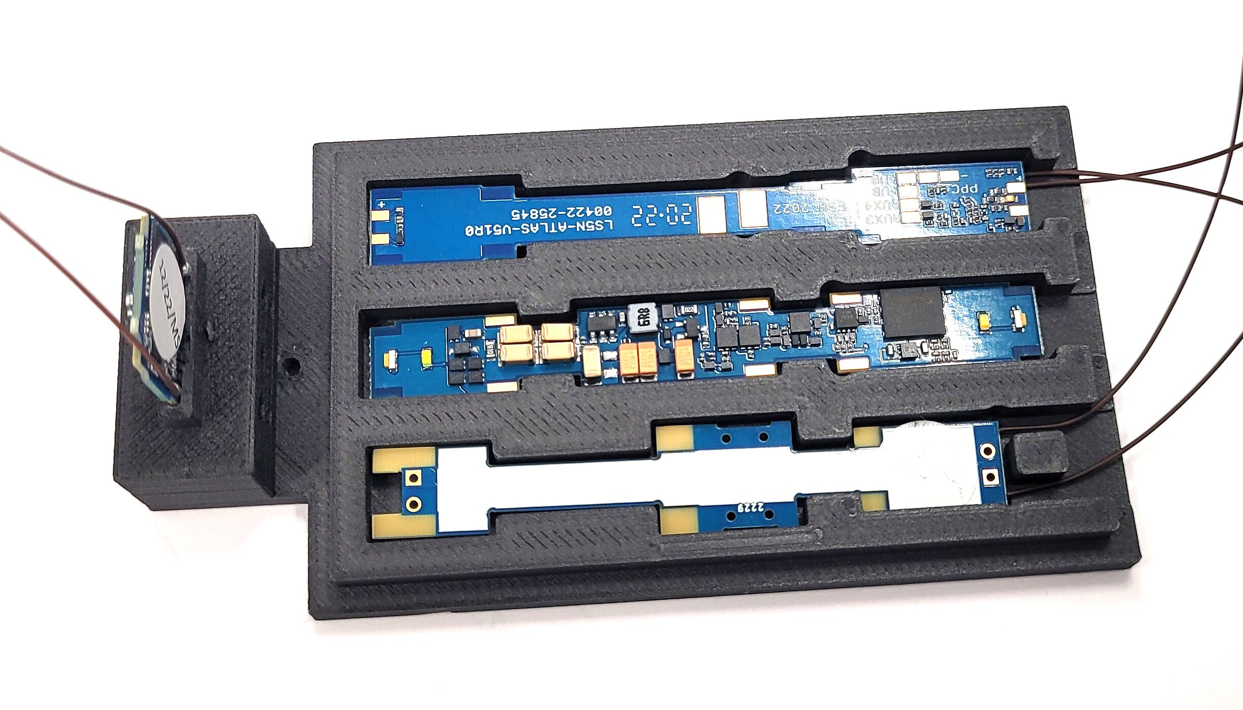
Streamlined Backshop offers custom Add-On Kits for the ESU 53900 LokTester. The product ships unassembled and requires basic DCC knowledge, soldering skills, and a bit of creativity to develop the interface to your test stand. The modules can be used with ZIMO MSTAP Decoder Testers or even as a stand alone device.
Instructions are admittedly limited. The product is of limited need and each installation is custom. I have provided a couple of images here to provide some general guidelines of how I have adapted these to my own programming station so simplify the task of programming here at SBS4DCC. You can literally use any Interface Connector available on the ESU 53900 LokTester... I eventually daisy-chained my kit into a single harness and hardwired it to the tester using the on-board screw terminal. A 21-pin connector the TCS 1358 21-HW - 21MTC Adapter Board (5-pk) - NEM660 21MTC to Hardwire works pretty well too.
Note that these modules are intended to simplify and improve productivity of programming sound files. They are not intended to test every single function of the decoder.
I currently offer the following versions...
SBS4DCC - ESU 53900 LokTester Decoder Test Module Add-On Kit for ESU 58721 58731 58741 58751
SBS4DCC - ESU 53900 LokTester Decoder Test Module Add-On Kit for 58821 58921
SBS4DCC - ESU 53900 LokTester Decoder Test Module Add-On Kit for ESU 58721 58731 58741 MX605 MX660
ASSEMBLY EXAMPLES
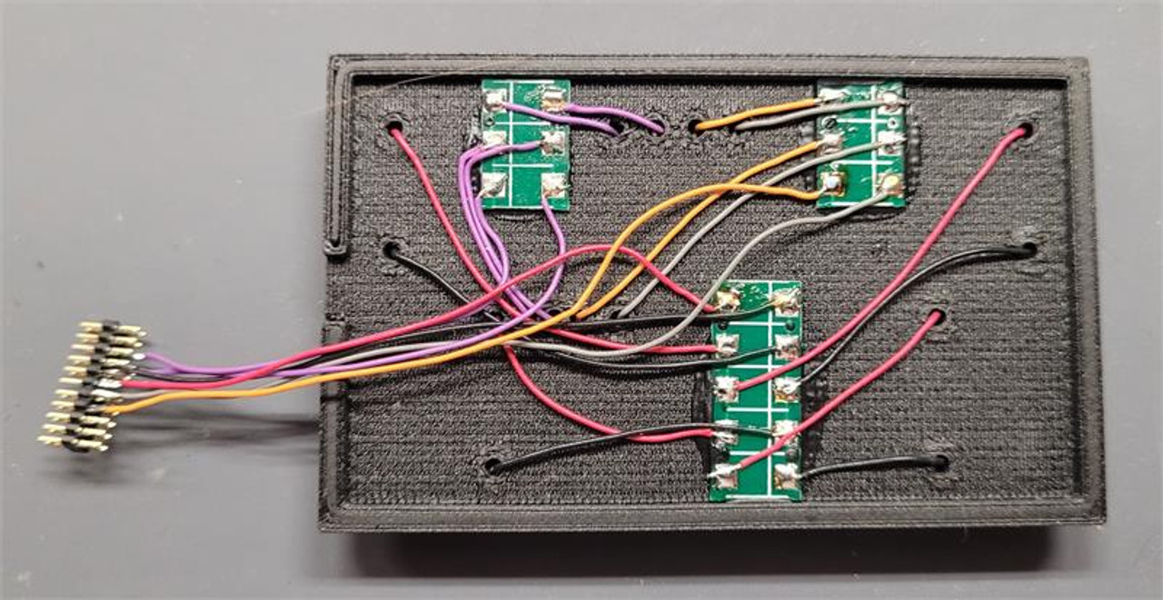
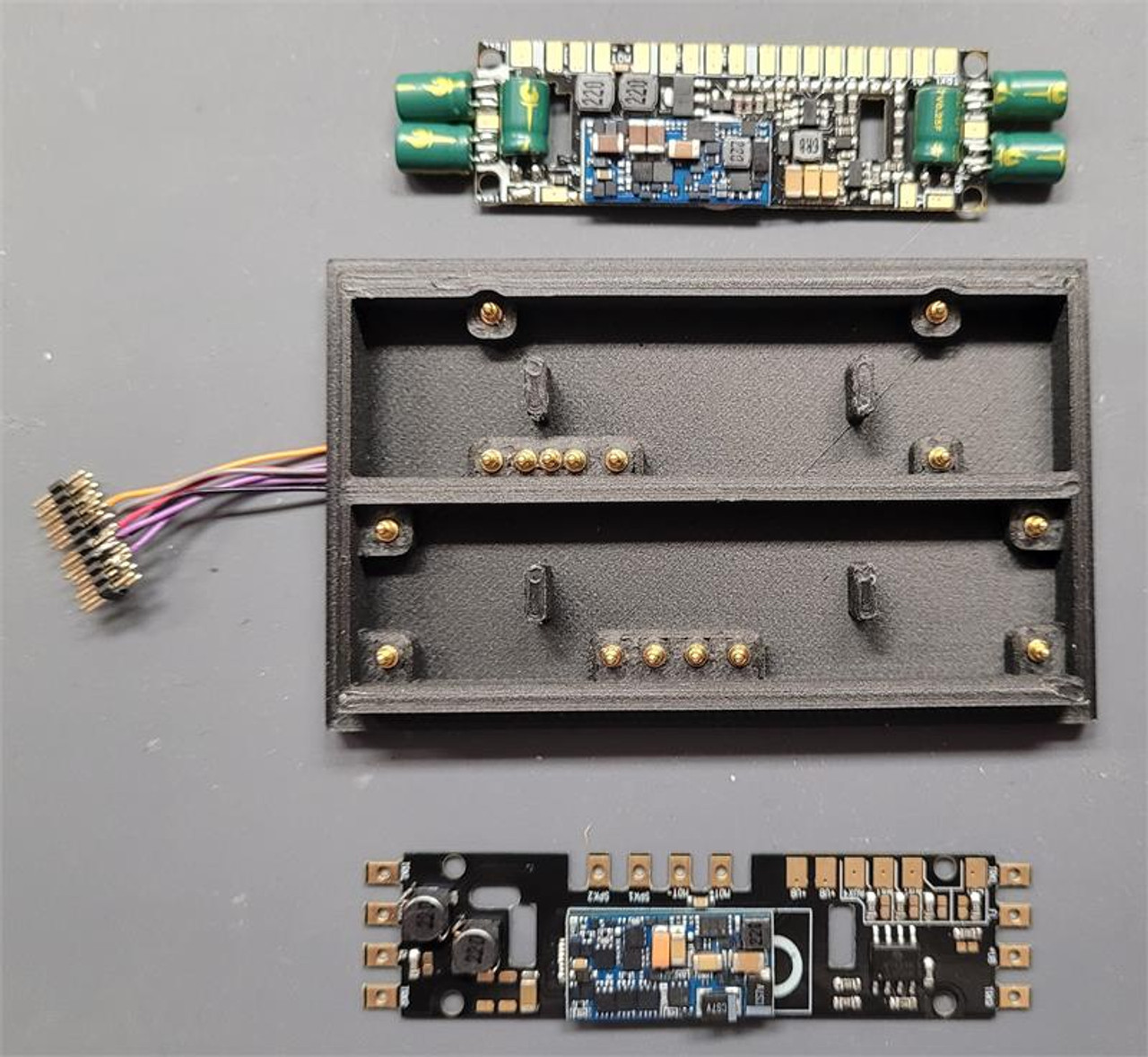
Assembly of the test module is pretty straight forward... attach decoder wire to the pogo pins then insert the pins in the top side of the module. I used circuit boards similar to the TCS 1518 4-Point Junction Board (25pk) to organize the wires and create a tidy, single wire harness to connect to a tester.
I wired the common connection from each pin group in series to the next pin group to minimize the volume of wire to manage.
There are four or six pins for each decoder type...
- Track power - Right (RED)
- Track power - Left (BLACK)
- Motor power - Pos (ORANGE)
- Motor power - Neg (GRAY)
- Speaker x2 - Right/Left (BROWN or VIOLET) - as required based on decoder type

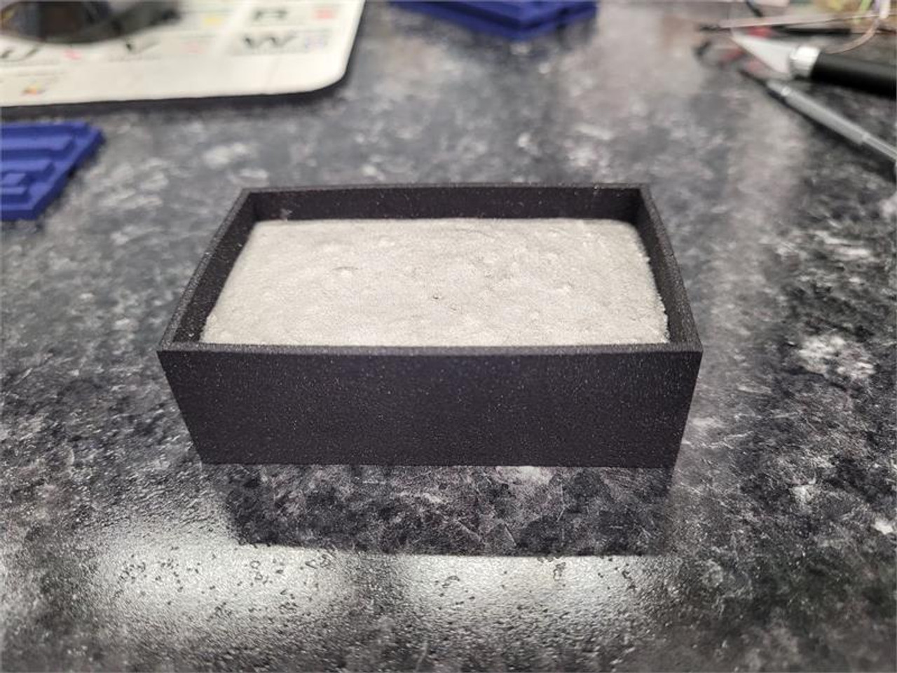
The weight box is just a simple, easy way to apply downward pressure on the decoder to improve continuity between the terminal on the decoder and the pogo pins. Use something heavy... I used Woods Metal because it is low temp and can be poured into the cavity to be custom fit to the shape.


