Atlas N Scale OEM E24 Circuit Boards - Decoded
Last Updated 250614
The ESU 58925 LokSound 5 Nano NMRA DCC Sound Decoder - ESU E24 Integral Connector is compatible with the circuit boards referenced on this page. CLICK HERE for a full list of compatible E24 decoders.
Originally posted on The Railwire: A Forum for Modelers by user peteski, last updated May 23, 2025, 06:53:54 PM.
This information is shared by and republished here with permission of author.
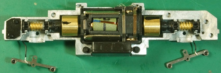
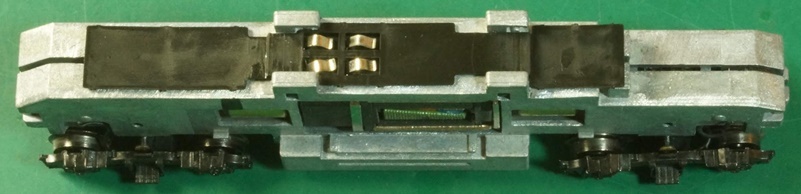
The board described in this post is used by Atlas in the locos with a new horizontally-split chassis with wired trucks first produced in 2024. So far it is used in 2023-2024 versions of SD7/9, GP7, GP9, RS-3, and RSD-4/5. There are couple variants. Part # on the boards is 1172-PC01 or AF1172-PC01 Each of those have connectors in slightly different locations, but electrically they are identical.
That new board is a bit of a mystery. It has two unused 4-pin connectors with very little information available about their purpose. I don't own any models with that board, and contacting Atlas to get some details about the electrical diagram did not yield any info (no reply from Atlas). Also, until recently I had no luck trying to borrow the board from TRW members until Benjamin volunteered to send me that board removed from one of his models. Thank you @GM50 4164 on behalf of all the TRW members looking for this info. With the board in hand, last Sunday I was able to decipher all the connections. There are some legends silk-screened by each connector, but they aren't very helpful in determined what AUX outputs they connect to.
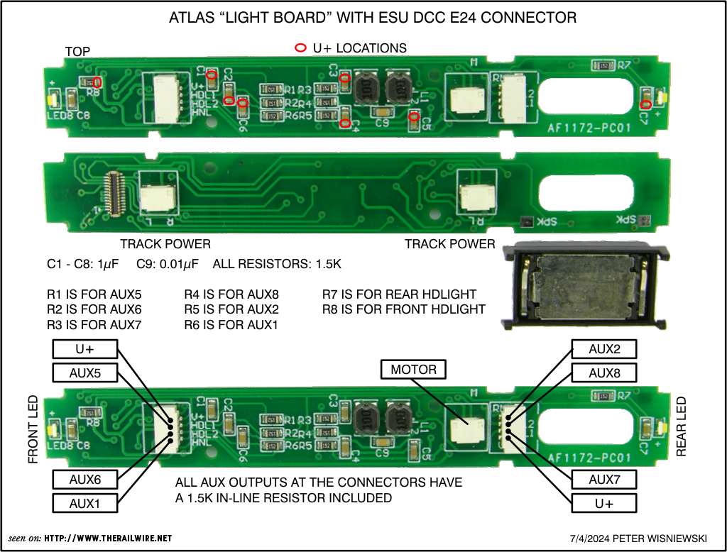
The diagram is pretty much self-explanatory. Each of the unused connectors provides access to three AUX outputs (with 1.5k ohm resistor in series) and a common positive (U+) or a "blue" connection.
For those interested in more details, here's a schematic diagram.
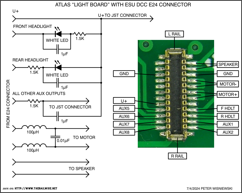
All the AUX outputs are powered (no logic level AUX outputs were made accessible), and all those AUX outputs include a series-connected 1.5k Ohm resistor. The resistor is on the negative leg of the circuit. The only exception is the hardwired rear headlight LED where the resistor is on the positive leg. That is inconsequential since the headlights are hardwired directly on the light board. Also curious fact is that there are 1µF capacitors wired in parallel with each LED to be connected to AUX output. These were likely added to prevent the LED flicker when dirty track caused the loco running in DC configuration to briefly lose track contact. When that occurs the still-rotating but unpowered motor generates BEFM high enough to cause white LEDs to briefly flicker. Those caps should not have any detrimental effect on the DCC lighting functions.
I also noticed that there is a RFI (Radio Frequency Interference) suppression filter included in the motor circuit. It consists of two 10µH inductors and a 0.01µF capacitor. Usually decoder manufacturers recommend removing such filters often included in many models, but here the circuit designer obviously chose specific values of those components not to interfere with the decoder's BEMF functionality.
I was also asked if the ground/common (GND) connection was available on the Atlas board, which along with the U+ raw rectifier voltage could be utilized for connecting a keep-alive circuit. Unfortunately, Atlas did not have enough foresight to include a GND solder pad on the decoder. It is too bad since GND is available on the E24 connector and only some minor design change of the PC board (with no additional cost) would have been needed to provide that.
As shown in the closeup photo of the E24 connector, 2 GND pins are there, but the solder pads are too short to be usable for soldering a GND wire at that location. Even if someone was able to solder a very thin wire to one of the connector's GND pins, that would not work. The mating connector on the decoder is wider than the one on this board, so when it's seated on the Atlas board, it leaves no clearance under it for any additional soldered wire.
If someone really wants to add a keep-alive circuit, the ground connection can be made directly to the decoder. The positive lead of a keep-alive will be attached to any of the U+ locations on the light-board, and the negative lead to any of the GND locations shown below.
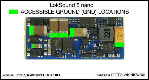
Of course soldering wires directly to the decoder components will void the warranty. Also five of the components I showed (on the left) are MLCCs (Multi-Layer Ceramic Capacitors). Those are made of a sandwich of hundreds of metalized ceramic leaves fused together, and they are sensitive to thermal shock which can cause microscopic fractures. That can occur when the caps are rapidly and unevenly heated from room temperature to solder-melting temperature (by heating up one of the metalized ends with a soldering iron). While damage is unlikely to happen, I felt that I should give a warning.
Since no logic-level AUX outputs are accessible , the ESU 3-wire Power Pack keep alive cannot be utilized, since the Power Pack's "control" lead (white wire) has to be connected to a logic-level AUX output. Only generic 2-wire keep-alives or simple capacitor circuits can be used (and those might affect programing of the decoder)
Last thing is what is needed to mate with those unused connectors to be able to connect more LEDs. Those on-board connectors are JST 0.8mm spacing male headers. There are mating female sockets are available as cable assemblies. They come in different lengths of wire with a female socket on both ends. Different lengths are available. A link to a 12" cable at Digikey: 455-2994-ND. Manufacturer's part# is A04SUR04SUR32W305B is someone wants to find another source. Basically to make that cable assy. usable, cut the wires half way between the connectors. That will yield 2 connectors with 6" wire pigtails.
Happy Independence day to our U.S. members!
The board described in this post is used by Atlas in some of the recently produced narrow hood locos with a vertically-split (conventional) chassis. It is installed in E24 decoder-ready DC locos like GP38 and possibly others. It has a dummy E24 DC plug factory installed for DC operation. This board does not have a visible part number.
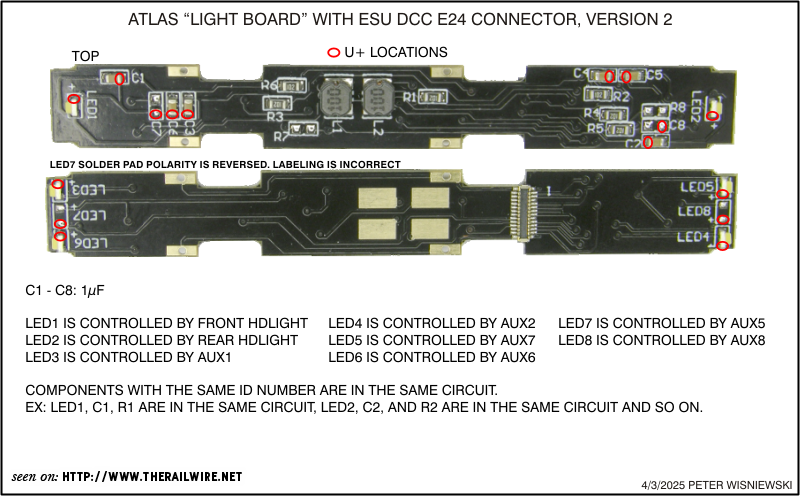
The diagram is pretty much self-explanatory. All on-board LEDs are connected in series with a 1k resistor, and also a 1µF capacitor in parallel with each LED. There is no dedicated U+ "blue" solder pad present, but the U+ voltage is accessible at multiple red-circled ends of the components on the board. Just solder a wire directly to one of those locations. Ideal locations for connecting to the U+ voltage are the appropriate pads of the unpopulated caps C7 and C8.
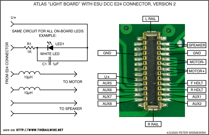
For those interested in more details, here's a basic schematic diagram.
All the AUX outputs are powered (no logic level AUX outputs were made accessible). Each resistor is connected on the negative side of LED. The 1µF capacitors wired in parallel with each LED were likely added to prevent the LED flicker when dirty track causes brief track connectiion loss with the loco running in DC configuration (running with the dummy E24 board). When that occurs the still-rotating but unpowered motor generates BEFM voltage high enough to cause white LEDs to briefly flicker. Those caps should not have any detrimental effect on the DCC lighting functions.
There is also a RFI (Radio Frequency Interference) suppression filter included in the motor circuit. It consists of two 10µH inductors. Usually decoder manufacturers recommend removing such filters incorporated into many models, but here the circuit designer obviously chose specific values of those components not to interfere with the decoder's BEMF functionality.
I was also asked if the ground/common (GND) connection was available on the Atlas light board, which along with the U+ raw rectifier voltage could be utilized for connecting a keep-alive circuit. Unfortunately, Atlas did not have enough foresight to include a GND solder pad on the decoder. It's too bad since GND is readily available on the E24 connector and only some minor design change of the PC board (with no additional cost) would have been needed to provide that.
As shown in the closeup photo of the E24 connector, two GND pins are there, but the solder pads and traces are too short to be usable for soldering a GND wire at that location. Even if someone was able to solder a very thin wire to one of the connector's GND pins, that would not work. The mating connector on the decoder is wider than the one on this board, so when it's seated on the Atlas board, it leaves no clearance under it for any additional soldered wire.
To add a keep-alive circuit, the ground connection will have to be made directly to the decoder. The positive lead of a keep-alive will be attached to any of the U+ locations shown on the light-board, and the negative lead to any of the GND locations shown below.
Of course soldering wires directly to the decoder's components will void the warranty. Also, five of the components I showed (on the left) are MLCCs (Multi-Layer Ceramic Capacitors). Those are made of a sandwich of hundreds of metalized ceramic leaves fused together, and they are sensitive to thermal shock which can cause microscopic fractures. That can occur when the caps are rapidly and unevenly heated from room temperature to solder-melting temperature (by heating up one of the metalized ends with a soldering iron). While damage is unlikely to happen, I felt that I should give a warning.
Since no logic-level AUX outputs are accessible, the ESU's 3-wire Power Pack keep-alive cannot be utilized, since the Power Pack's "control" lead (the white wire) has to be connected to a logic-level AUX output. Only generic 2-wire keep-alives or simple capacitor circuits can be used (and those might affect ability to programing the decoder).
There is an alternative to just remove the Atlas E24 board and replace it with ESU 58721 LokSound 5 Decoder. It's a direct replacement of the light board. The cost of 58721 is very similar to a LokSound5 nano decoder needed for the Atlas loght board. Access to GND in easy on 58721 but accessing U+ is not convenient. For more info about 58721 click on this link.
The speaker is in the fuel tank and the electrical contact strips are routed around the motor to the top of the chassis.
Good photos of that setup are on the Spookshow website https://spookshow.net/loco/atlasgp3840.html