ESU - Electronic Solutions Ulm
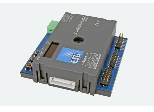
ESU 51830 SwitchPilot 3 DCC Accessory Decoder
- UPC:
- 4044645518304
- MPN:
- 51830
- Condition:
- New
Save More With Volume Discounts…
| Buy 5 - 9 | $31.59 each |
| Buy 10 or above | $30.62 each |
Description
SwitchPilot 3 decoders are optimized for stationary use on your system and can switch conventional double coil switch drives, light signals, magnetic uncouplers, light bulbs or other stationary consumption.In order to facilitate the rather cumbersome configuration of magnetic article decoders, the SwitchPilot 3 has an innovative operating concept consisting of a 4-line, illuminated OLED display and three input buttons.
Modes
The SwitchPilot 3 is multi-protocol and can be used with workstations according to the Märklin® Motorola® system (e.g. 6021, Central Station® or Mobile Station®) as well as DCC-enabled control panels. The configuration can take place on both the main track and the programming track. Thanks to RailCom®, CVs can also be read out.
Functioning
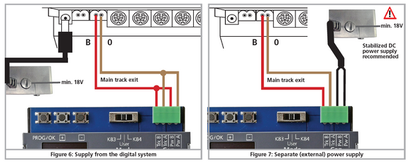
The SwitchPilot 3 can be supplied directly from the digital system or from an external DC or change voltage source. It has a total of 8 transistor outputs, which are grouped in the 4 exit pairs 1 to 4. Each output pair contains two outputs (OutA and OutB) and can be configured individually for the desired use case:In pulse mode, the output is switched on as soon as a switching command is received. The fact that the output automatically switches off again as soon as the time stored in the decoder has elapsed prevents the burning of magnetic article drives.At the moment (K83-compatible) the output remains active as long as the button on the control panel is pressed. This operating mode is suitable for turnout drives with final shutdown or for de-caps.In bi-stable continuous operation (k84-compatible), the two outputs are switched on and off: When pressing the first button (red) on the control panel, the output Out A is switched on. It remains active until pressing the assigned button (green) activates the output Out B of the same output group. Out A and Out B behave like a change switch.In alternating flasher mode, the outputs Out A and Out B of an output pair are switched on alternately with an adjustable flashing frequency. The change indicator is started with the command "Ge- rade/Green" of the assigned button and stopped again with the command "Branching/Red".Optionally, the output can also be slowly dimmed and dimmed (so-called "zoom" for glow lam pen simulation).With the switch 3 mode switch, you can switch all output pairs together to the "k83" or "k84" modes at lightning speed, regardless of how they are configured.
Feedback
Since the SwitchPilot 3 is RailCom®-capable, all settings can be read out and changed directly in the built-in state on request. In combination with an ECoS as an ideal "partner", the SwitchPilot 3 can record and display the actual turnout setting with appropriately prepared turnout drives. Finally, you have the certainty that your switch has switched correctly!
Set
The SwitchPilot 3 can be flexibly adjusted either on the programming track with DCC control panels or on the main track with POM ("Programming on Main") or can also be read out via RailCom® CVs. On request, he also learns the addresses directly via a programming button. The easiest way to set is, of course, with the integrated OLED display and the three input buttons: All (!) Settings can be checked directly on the decoder and changed on request. A"Programming" with the help of your control panel is not required. It really can't be any easier. The ESU LokProgrammer can be used for firmware updates.
Protection
As with our locomotive decoders, the outputs of the SwitchPilot 3 are largely protected against overload. We want you to enjoy your decoder for as long as possible.
Additional Resources
MANUFACTURERS WEBSITE: |
|
SOUND CONFIGURATION & SOUND FILE RESOURCES: |
|
FIRMWARE & SOFTWARE RESOURCES: |
|
PRODUCT MANUALS & TECHNICAL DOCUMENT RESOURCES: |
|
MANUFACTURERS WARRANTY & REPAIRS: |
|
ADDITIONAL INFORMATION - DCC TIPS: |
|
ADDITIONAL INFORMATION (1): |
|
ADDITIONAL INFORMATION (2): |
Additional Information
PRODUCT CLASS : |
All Scales |
DECODER TYPE: |
Accessory - Switch |
DECODER INTERFACE (PRIMARY): |
Screw Terminal |
DECODER INTERFACE (SECONDARY): |
NA |
SIZE-INCH (L x W x H): |
3.39 x 3.39 x 0.98 in |
SIZE-METRIC (L x W x H): |
86 x 86 x 25 mm |
FUNCTION CURRENT: |
1.5 A continuous |
TRACK SECTION INPUT-OUTPUT: |
0 |
CIRCUIT BREAKER: |
NA |
AUTO REVERSER: |
NA |
OCCUPANCY DETECTION: |
NA |
FUNCTION CONTROL INPUTS: |
0 |
SWITCH MOTOR FUNCTION OUTPUTS: |
4* |
STATIONARY - SIGNAL LIGHTING FUNCTION OUTPUTS: |
8* |
SWITCH MOTOR TYPE - STALL MOTOR (TORTOISE SLOW-MOTION): |
NO |
SWITCH MOTOR TYPE - TWIN COIL SOLENOID (ATLAS SNAP): |
YES |
SWITCH MOTOR TYPE - BI-POLAR SOLENOID (KATO-PIKO-LGB): |
NO |
SWITCH MOTOR TYPE - SERVO MOTOR: |
NO |
PROTOCOL: |
NA |
BI-DIRECTIONAL COMMUNICATION: |
RailCom |
ADDITIONAL FEATURES: |
NA |
NOTES (1): |
* Optional configuration - see manual |
NOTES (2): |
NA |


