Description
RR-CirKits FOB-A Direct Drive Fan Out Board for LEDs
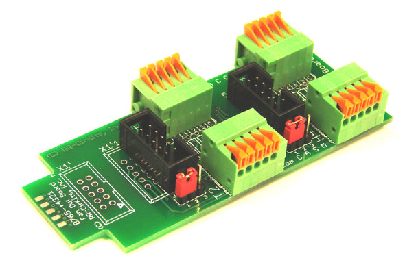
This board is specifically designed to direct drive eight LED's from a single RR-CirKits port. It includes on board locations for current limiting resistors and jumpers to select common anode or common cathode connections. No extra hardware is required at each signal head. It may also be used to simplify connections to the 10 wire ribbon cables for multiple input connections. Quick release compression connectors simplify repeated connection of #18 and smaller wires.
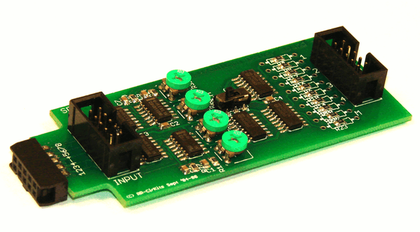
All RR-CirKits Tower Controller I/O modules are designed to either be plugged directly into the TC-64, or else mounted in Tyco 3-1/4" Snap-Track® mounted to the bench work and connected with short ribbon cables. (Snap-Track® is a plastic channel designed to mount PC cards to a chassis, not something to run trains on.) This I/O module is equipped with three connectors to facilitate these connection options and allow for pass through wiring.
FOB-A (8 line Fan Out Board)
The FOB-A board contains 2 five output compression connectors. Each individual line has a position to mount a series limiting resistor for individual LEDs. Each common connection may be jumper selected as +5 volts or Ground.
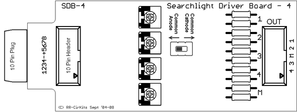
The FOB-A may be used as a fan out point for a TC-64 port, or as a connection point for up to 4 two or three wire searchlight signals driven by a SDB-4 Searchlight Driver Board. The output compression connectors used on this board allow connections to wire from #18 AWG to #40 AWG. For smaller wire sizes, first press back on the orange lever to release, then poke home the wire. Release the lever, and gently pull on the wire to be sure it was captured properly.
The FOB-A input lines may be used as active low or active high as determined by the common connection jumper selections. The TC-64 should be configured as "Driver" for any port that is directly connected to a FOB-A driving LEDs. The FOB-A may also be used as a collection point for input contacts or sensors. In that case use jumpers or low value resistors in the resistor points and Gnd (cc) on the common connection jumper blocks.
Additional Resources
MANUFACTURERS WEBSITE: |
|
SOUND CONFIGURATION & SOUND FILE RESOURCES: |
|
FIRMWARE & SOFTWARE RESOURCES: |
|
PRODUCT MANUALS & TECHNICAL DOCUMENT RESOURCES: |
|
MANUFACTURERS WARRANTY & REPAIRS: |
|
ADDITIONAL INFORMATION - DCC TIPS: |
|
ADDITIONAL INFORMATION (1): |
|
ADDITIONAL INFORMATION (2): |
Additional Information
PRODUCT CLASS : |
All Scales |
SIZE-INCH (L x W x H): |
0 x 0 x 0 in |
SIZE-METRIC (L x W x H): |
0 x 0 x 0 mm |
ADDITIONAL FEATURES: |
NA |
NOTES (1): |
NA |
NOTES (2): |
NA |


