Description
RR-CirKits SDB-4 4-Output Searchlight Driver Board
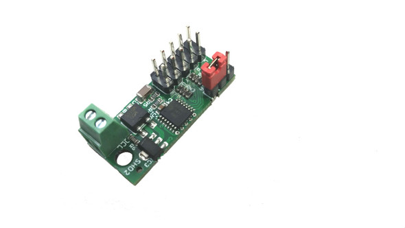
This 4 output board is specifically designed to directly drive 4 four aspect signals utilizing bi-polar or three wire LED's and includes a yellow color balance control for each of the four signal heads. The 4 LEDs connect using a single 10 wire ribbon cable. A BOB-S can simplify connecting the signal masts.
Normally used with Tower LCC, TowerMan, or TC Mark-II interface.
All RR-CirKits Tower Controller Modular I/O cards are designed to either be plugged directly into the TC-64, or else mounted in Tyco 3-1/4" Snap-
Track® mounted to the bench work and connected with short ribbon cables. (Snap-Track® is a plastic channel designed to mount PC cards to
a chassis, not something to run trains on.) Each Modular I/O card is equipped with two connectors to facilitate these connection options.
SDB-4 (Searchlight Signal Driver - 4 head)
One of the best descriptions of CTC signalling from both a modeller's and prototype perspective that I am aware of may be found at the Control Train Components web site. (http://www.ctcparts.com/aboutprint.htm)
Power Connections
This Modular I/O board gets its power directly from the Tower Controller. It includes on-board oscillators for each signal to adjust the color balance
between the Red and Green LED chips to get an acceptable Yellow.
Do NOT use this board to drive anything other than dual color LEDs, and do NOT connect either the LEDs nor other board outputs to anything other than each other. Bi-polar LEDs do not have a common connection, and may not be tied to a signal mast nor to each other.
Signal Head Wiring
Single connectors are shown in these schematic drawings, but normally each signal mast will have its own connector spaced out in daisy chain
configuration along a single ribbon cable coming from the driver card.
All the following circuits may be built as either common anode or common cathode versions. Simply switch the polarity selector on the driver board
to match. The typical common cathode versions are shown. To wire for common anode versions just reverse the direction of each LED and
connect the common lines to pin 6.
Additional Resources
MANUFACTURERS WEBSITE: |
|
SOUND CONFIGURATION & SOUND FILE RESOURCES: |
|
FIRMWARE & SOFTWARE RESOURCES: |
|
PRODUCT MANUALS & TECHNICAL DOCUMENT RESOURCES: |
|
MANUFACTURERS WARRANTY & REPAIRS: |
|
ADDITIONAL INFORMATION - DCC TIPS: |
|
ADDITIONAL INFORMATION (1): |
|
ADDITIONAL INFORMATION (2): |
Additional Information
PRODUCT CLASS : |
All Scales |
SIZE-INCH (L x W x H): |
0 x 0 x 0 in |
SIZE-METRIC (L x W x H): |
0 x 0 x 0 mm |
ADDITIONAL FEATURES: |
NA |
NOTES (1): |
NA |
NOTES (2): |
NA |


