


Description
RR-CirKits Signal LCC-P
Signal LCC-P LCC (Layout Command and Control 8 line Input Output board Plus 16 LED Driver with special effects
Signal LCC-P features:
- 16 Led drivers plus 8 line Input/Output node for NMRA CAN bus LCC®.
- Logic level I/O port compatible with other standard RR-CirKits I/O modules.
- Boot Loader for user installable firmware upgrades.
- Includes powerful internal Logic Elements.
- Compatible with JMRI.
- Small package size. Just 1-¾" x 3-1/4" x 5/8".
- POC (Powered Over CAN) LCC® connections. Note: Requires a powered LCC bus. [20 ma. bus load] (plus any I/O load current such as LEDs)
- Dual 10 pin headers for LED connections.
12 Signal LCC compatible Input/Output Cards
The RR-CirKits Signal LCC and its compatible I/O modules are designed to be clipped into Tyco 3-1/4" Snap-Track® mounted to the bench work. (Snap-Track® is a plastic channel designed to mount PC cards to a chassis, not something to run trains on.)
A single Signal LCC or compatible I/O module fits into the 3TK2-1 (single) mounting track. Other widths are available for compact installations using multiple boards. A common interlocking installation would use a double mounting track.
Each I/O module is equipped with connectors to facilitate these I/O board connections. Use IDC connectors and ribbon cables to connect the Signal LCC to the I/O cards.
12.1 BOD4-CP (DCC 4 Block Occupancy Detector – Dual Turnout Driver)
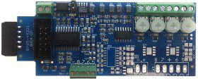
The BOD4-CP is designed to augment the Signal LCC in order to do all of the primary functions required at a typical interlocking. (Control Point) The BOD4-CP does not expect you to re-wire your layout to bring track feeders to remotely located detector cards. The small CT (Current Transformer) detection coils are placed directly on the track feeders where they belong. A short length of Cat-5 cable is the usual way to carry the detected current back to the detector boards. The use of CT coils means that there are no track voltage losses associated with the detectors. Normal detection levels are 1mA. but may be adjusted to higher levels with on board pots.
During a DCC bus power failure the Power-Lok input on the BOD4-CP instantly locks the present state of each block detector. I.e. the state of the layout does NOT change during a DCC power outage, neither to all occupied, nor to all vacant. It just suspends the sending of any occupancy changes until after power is restored and the layout has stabilized again. If you do not want to use the Power-Lok feature, there is a jumper to disable it.
The BOD4-CP outputs are low during detection so the Signal LCC should be configured accordingly.
The BOD4-CP also includes two dual output turnout drivers and 4 input lines. To take advantage of this dual use the Signal LCC output section needs to be configured as ‘Sample’ mode. The BOD4-CP includes a screw terminal strip to connect 4 logic level input lines. These lines include internal 10K ohm pull up resistors to +5V, and may be driven by logic level circuits or contacts.
It is designed to drive stall motor turnout machines such as those found in Tortoise® and Switchcraft® machines. It is also suitable for the higher current required by the MTB-MP1 and MTB-MP5 machines. The BOD4-CP Output section is also able to drive solenoid coils or other high voltage medium power devices. Normally the input voltage should not exceed 27VDC. The BOD4-CP board is optically isolated from the driving circuitry to protect the Signal LCC-32H or other control device from these high power outputs. When driving stall motors, single coils or high power loads configure the lines as a steady output.
By using the proper options on the Signal LCC, the SCSD-8 may also be used to control dual coil momentary switch machines. In 'Dual Coil' mode the output lines must be paired such that each pair of lines requires just a single event pair. However reverse the two EventIDs. This action will normally require a 0.1 second pulse when driving solenoids.
The lines are paired and only the primary event of the first line of each pair will be used to trigger a pulse.
Dual coil operation should not be attempted if the switch machine power supply is not of the capacitive discharge type that will limit the long term current to a low value, or contains proper fusing, in case of hardware or configuration errors.
Failure to observe this precaution may result in destruction of equipment and could be a fire hazard!
The BOD4-CP is not designed to drive last generation dual coil (Kemtron style) switch machines that require over 3A to operate properly. The BOD4-CP output current is internally limited to approximately 3A and these old machines will not operate reliably, if at all. Use an SCSD-8, RB-4, or else install more modern machines.
12.2 BOD4 (DCC 4 Block Occupancy Detector)

The BOD4 is the detector only version of the BOD4-CP. It is designed to augment the Signal LCC with 4 detection blocks when no high current turnout drivers are required. The BOD4 does not expect you to re-wire your layout to bring track feeders to remotely located detector cards. The small CT (Current Transformer) detection coils are placed directly on the track feeders where they belong. A short length of Cat-5 cable is the usual way to carry the detected current back to the detector boards. The use of CT coils means that there are no track voltage losses associated with the detectors. Normal detection levels are 1mA. but may be adjusted to higher levels with on board pots.
During a DCC bus power failure the Power-Lok input on the BOD4 instantly locks the present state of each block detector. I.e. the state of the layout does NOT change during a DCC power outage, neither to all occupied, nor to all vacant. It just suspends the sending of any occupancy changes until after power is restored and the layout has stabilized again. If you do not want to use the Power-Lok feature, there is a jumper to disable it.
The BOD4 outputs are low during detection so the Signal LCC should be configured accordingly..
The BOD4 also includes a screw terminal strip for easy connections to the 4 unused Signal LCC logic level I/O lines.
12.3 BOD-8 (DCC Block Occupancy Detector - 8 block)
The BOD-8 does not expect you to re-wire your layout to bring track feeders to the detector cards. The small CT (Current Transformer) detection coils are placed directly on the track feeders where they belong. Simple lengths of Cat-5 cable are the usual way to run the signals back to the detector boards. Use of CT coils means that there are no track voltage losses associated with the detectors. Normal detection levels are 1mA. but may be adjusted to higher levels with on board pots.
During a DCC bus power failure the Power-Lok input on the BOD-8 instantly locks the current state of each block detector. I.e. the state of the layout does NOT change during a DCC power outage, neither to all occupied, nor to all vacant. It just suspends sending any occupancy changes until after power is restored and things have stabilized again. If you do not want the feature there is a jumper to disable it.
The BOD-8 outputs are low during detection so the Signal LCC should be configured accordingly.
12.3 OIB-8 (Opto Isolator Board - 8 input)
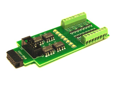
This 8 input board is used when a non-isolated source of voltage needs to be monitored and input to the Signal LCC. One example would be to monitor the DCC voltage on a set of points to determine the position of a turnout without using auxiliary contacts.
This board may be configured to monitor the absence or presence of an AC or DC signal. This board requires 10mA. for reliable operation and includes built in current limiters. It is often used for detection on three rail systems by isolation of one rail.
12.4 SMD-8 (Stall Motor Driver – 8 line)
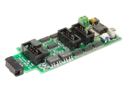
The SMD-8 board contains 8 individual, optically isolated, HBridge drivers. This allows the board to be powered from any supply between 9 Volts and 27 Volts. It is primarily designed to drive stall motor turnout machines such as those found in Tortoise® and Switchcraft® machines. It is also suitable for the higher current required by the MTB-MP1 and MTB-MP5 machines. Do not exceed 20VAC or 27VDC at the power input.
This board includes an adjustable buck switching regulator to allow you to control the speed of your switch machine motors. This regulator can not boost the drive voltage above the supply voltage.
12.5 RB-4 (Relay Board - 4 x SPDT)
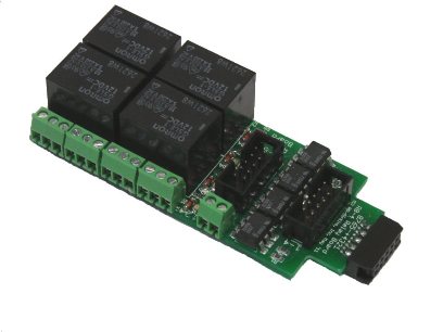
Relay Board - 4 is a Quad 10A SPDT relay board with logic level drivers. It is suitable for use with Signal LCC or other logic level output devices. It requires 12V auxiliary power to drive the relay coils. Auxiliary power is optically isolated from the logic inputs for double isolation. LED indicators for each relay make it easy to monitor activity.
Includes dual ribbon connectors with offset lines to allow easy connection as output 1-4, or output 5-8, from the Signal LCC, or other driver.
The RB-4 may be connected in parallel with a BOD4 when detection plus high current outputs are required. Use a single 10 wire flat ribbon cable with 3 IDC connectors, and connect it to the 5-8 input.
The RB-4 input lines are active low so all lines on this Signal LCC port should be configured appropriately. This inverted input mode matches most types of driver outputs, and the drive polarity may be easily switched either in the Signal LCC configuration or by reversing the RB-4 output contacts.
12.6 BOB-S (Break Out Board)
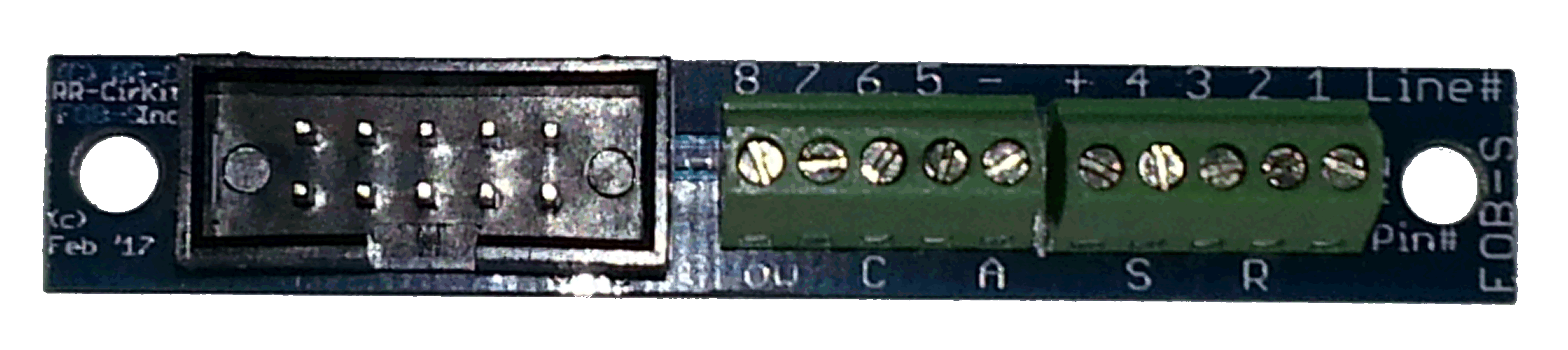
This board is a convenient way to convert from 10 pin ribbon cable to screw terminals. It may be used for inputs or outputs.
For input lines do not exceed 5V on any input or the Signal LCC will be damaged.
Additional Resources
MANUFACTURERS WEBSITE: |
|
SOUND CONFIGURATION & SOUND FILE RESOURCES: |
|
FIRMWARE & SOFTWARE RESOURCES: |
|
PRODUCT MANUALS & TECHNICAL DOCUMENT RESOURCES: |
|
MANUFACTURERS WARRANTY & REPAIRS: |
|
ADDITIONAL INFORMATION - DCC TIPS: |
|
ADDITIONAL INFORMATION (1): |
|
ADDITIONAL INFORMATION (2): |
Additional Information
PRODUCT CLASS : |
All Scales |
SIZE-INCH (L x W x H): |
0 x 0 x 0 in |
SIZE-METRIC (L x W x H): |
0 x 0 x 0 mm |
ADDITIONAL FEATURES: |
NA |
NOTES (1): |
NA |
NOTES (2): |
NA |
Related Products


RR-CirKits Signal LCC-S
RR-CirKits


RR-CirKits Signal LCC-32H
RR-CirKits


RR-CirKits LCC Repeater
RR-CirKits


RR-CirKits LCC VampMeter
RR-CirKits


RR-CirKits Tower LCC
RR-CirKits