Description
TCS 1599 LT-50 Facia LT Panel
This product is used with the LT-50 "Layout Throttle." This panel can be used to create a DCC track output when used with an LT-50 using the specified jack. A single additional wired LCC throttle can be connected to the front of the panel, and this panel can be connected into a larger LCC network using the jacks on the back. This panel can also be used as a power injection point for an LCC network (400mA per port) when used with an appropriate power supply (not included).
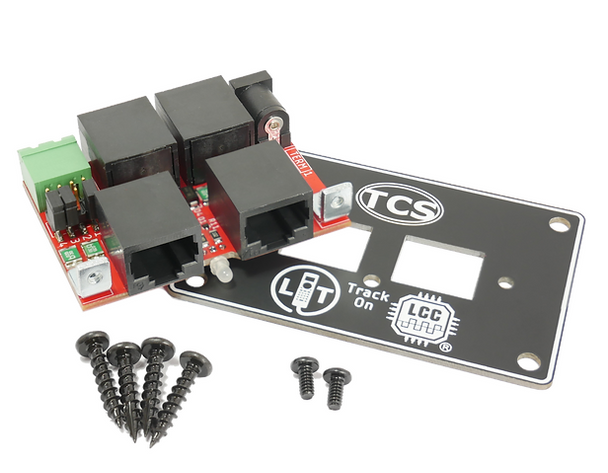
The LT Panel has a few notable physical features:
- Green 2-pin Track Output connector with detachable screw terminal connector
- 2.5mm x 5.5mm barrel jack for Power In
- Configuration Jumpers (see details below)
- Single "LT" RJ-45 jack(for LT-50 only)
- Three "LCC" RJ-45 jacks (1x Front: For T-50; 2x Rear for LCC Bus)
- Bi-color LED for "Track On"
Package Includes:
- LT Panel board x1
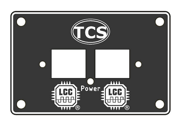
- LT Panel fascia cover plate x1
- Fascia mounting screws x4
- Fascia cover plate screws x2
- Option Jumpers x3
Specifications:
- Front facing LCC Power Injection Mode - 400mA combined
- Rear facing LCC Power Injection Mode - 400mA each
- LCC Power Consumption (self) = 10mA
- Power Supply Barrel Jack - 2.5mm ID x 5.5mm OD, center positive, outside negative.
Installation:
How to install the LT Panel
- Cut a square hole in your fascia with a width of ~2.75 inches and a height of ~0.75 inches.
(Min Width = 2.5in; Max width =2.9in; Max Height =1.8in) - Align the small hole on the fascia cover plate to the indicator LED before screwing it onto the panel board using the included screws. You can flip the fascia cover plate over for upside-down installation. The cover plate has been desinged so that it cannot be installed incorrectly. The "LT" logo will always indicate the correct jack for the LT-50 regardless of the orientation.
- Use the four included self-tapping wood screws to secure the assembled LT Panel into your fascia.
- Plug in the LT-50 power supply (optional; not included).
- Plug an LT-50 into the socket labeled “LT” to use as a command station.
It is not recommended to use this product in the same LCC network as a CS-105. Do not install more than one LT panel on a single layout - use SKU:1598 "LCC Throttle Panel"
The front-facing LCC socket can be used for additional throttles. An LT-50 plugged into the front-facing LCC socket will function as a throttle only.
Additional Resources
MANUFACTURERS WEBSITE: |
|
SOUND CONFIGURATION & SOUND FILE RESOURCES: |
|
FIRMWARE & SOFTWARE RESOURCES: |
|
PRODUCT MANUALS & TECHNICAL DOCUMENT RESOURCES: |
|
MANUFACTURERS WARRANTY & REPAIRS: |
|
ADDITIONAL INFORMATION - DCC TIPS: |
|
ADDITIONAL INFORMATION (1): |
|
ADDITIONAL INFORMATION (2): |
Additional Information
PRODUCT CLASS : |
All Scales |
SIZE-INCH (L x W x H): |
0 x 0 x 0 in |
SIZE-METRIC (L x W x H): |
0 x 0 x 0 mm |
ADDITIONAL FEATURES: |
NA |
NOTES (1): |
NA |
NOTES (2): |
NA |


