Description
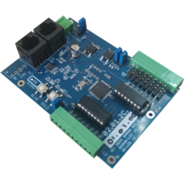
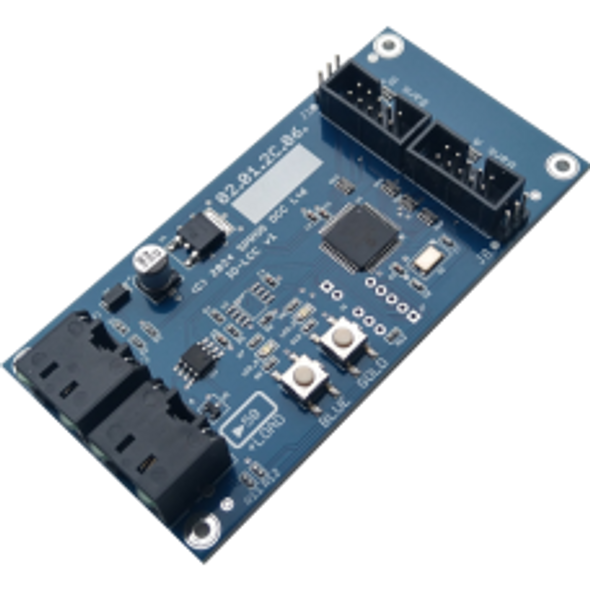
SPROG LCC SERVOIO-LCC Network Servo & IO Interface Module
To be successful in using the SERVOIO-LCC you should be familiar with basic LCC topics, e.g. see the Introduction to LCC/OpenLCB https://www.sprog-dcc.co.uk/downloads/lcc/lcc-basics.pdf on our website.
You will also need some familiarity with the JMRI software to connect to, and configure the SERVOIO-LCC. A computer connection is not required for operation.
NOTE: This document should be read in conjunction with the SERVOIO-LCC Errata, which may be downloaded from our website, for a list of known and fixed issues for this release.
Features
The main features of the SERVOIO-LCC are
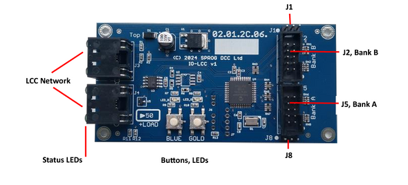
- Two I/O banks of eight channels for a total of sixteen channels
- Eight servo outputs on bank A only
- Three-pin headers for servo outputs on bank A
- Event generation for servo start-, mid- and end-points
- Servo positions saved between power cycles
- Eight individual logic level I/O channels per bank
- Optional high voltage (50 V max)/high current (500 mA max per channel) output per bank
- Jumper selectable pull-up/down for I/O channels
- Flexible configuration through the CDI (Configuration Description Information)
- Two status LEDs configurable through the CDI
- Two pushbuttons configurable through the CDI
- Can consume own generated events for event chaining (secondary events)
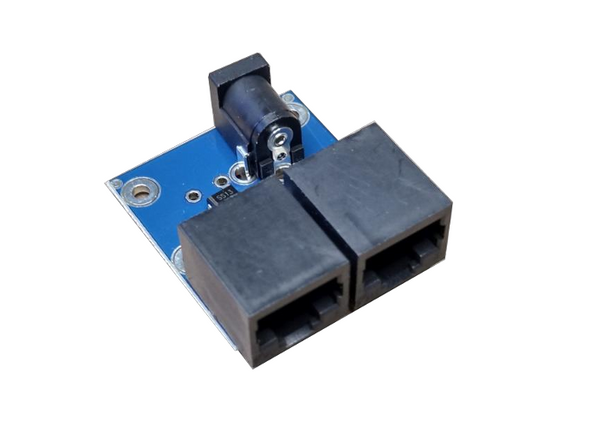
- Dual RJ45 for network pass-through or terminator
- Powered from the LCC network for simple I/O
- Auxiliary power input for servos and high-power option
- Bootloader for firmware updates
When using servos on bank A, all I/O channels on bank A are servo control outputs. They may not be used for other output functions, nor as inputs.
When using the high current drives on a bank, all output channels in the bank are outputs. They may not be used as inputs.
Electrical Specifications
The SERVOIO-LCC uses two sources of power: from the LCC network and from the auxiliary power connector.
For simple logic-level I/O, the power can be taken from the LCC network.
For higher powered I/O using the optional driver chips, or for servo operation, power must be supplied via the auxiliary power connecter in addition to the LCC network.
The SERVOIO-LCC consumed less than 50 mA from the LCC network. Additional loads taking power from the network must be added to this when calculating the total power budget for the LCC network.
Simple I/O
Each I/O channel can source or sink 50 mA, absolute maximum. The total allowed across all I/O is 350 mA, absolute maximum. In practice, currents should be kept much less than these limits. LEDs, for example, are usually bright enough with just a few mA of current.
Optional High Power Drivers
When the optional Toshiba TDB62083APG are used the maximum current per I/O channel is 500 mA but this must be reduced when multiple output are driving simultaneously, to limit the overall power dissipation within the device. Please consult the TDB62083APG data sheet.
Additional Resources
MANUFACTURERS WEBSITE: |
|
SOUND CONFIGURATION & SOUND FILE RESOURCES: |
|
FIRMWARE & SOFTWARE RESOURCES: |
|
PRODUCT MANUALS & TECHNICAL DOCUMENT RESOURCES: |
|
MANUFACTURERS WARRANTY & REPAIRS: |
|
ADDITIONAL INFORMATION - DCC TIPS: |
|
ADDITIONAL INFORMATION (1): |
|
ADDITIONAL INFORMATION (2): |
Additional Information
PRODUCT CLASS : |
All Scales |
SIZE-INCH (L x W x H): |
0 x 0 x 0 in |
SIZE-METRIC (L x W x H): |
0 x 0 x 0 mm |
ADDITIONAL FEATURES: |
NA |
NOTES (1): |
NA |
NOTES (2): |
NA |
